|
1
|
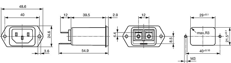
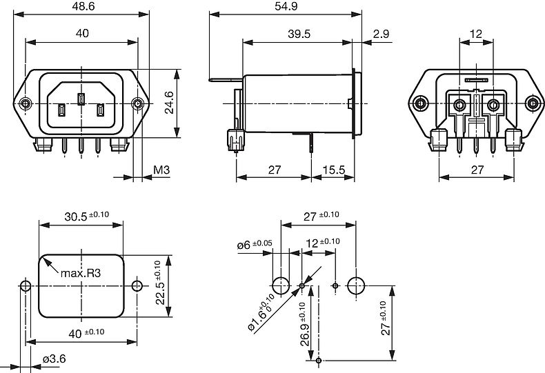
Standard version
|
Snap-in
|
Front Side
|
Quick connect terminals 6.3 x 0.8 mm
|
I
|
• |
5123.2000.0
|

|
|
10 |
|
|
2
|
Standard version
|
Snap-in
|
Front Side
|
Quick connect terminals 6.3 x 0.8 mm
|
I
|
• |
5123.2001.0
|

|
|
10 |
|
|
4
|
Standard version
|
Snap-in
|
Front Side
|
Quick connect terminals 6.3 x 0.8 mm
|
I
|
• |
5123.2003.0
|

|
|
10 |
|
|
6
|
Standard version
|
Snap-in
|
Front Side
|
Quick connect terminals 6.3 x 0.8 mm
|
I
|
• |
5123.2004.0
|

|
|
10 |
|
|
10
|
Standard version
|
Snap-in
|
Front Side
|
Quick connect terminals 6.3 x 0.8 mm
|
I
|
• |
5123.2006.0
|

|
|
10 |
|
|
15
|
Standard version
|
Snap-in
|
Front Side
|
Quick connect terminals 6.3 x 0.8 mm
|
I
|
• |
5123.2007.0
|

|
|
10 |
|
|
6
|
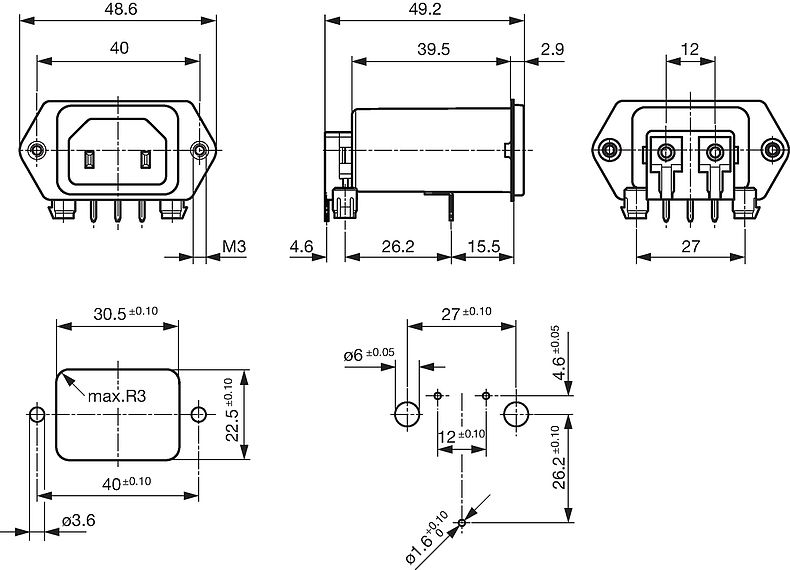
Standard version
|
Screw/PCB
|
Rear Side
|
PCB pin and earth pin 6.3 x 0.8
|
I
|
• |
5123.4074.0
|

|
|
10 |
|
|
1
|
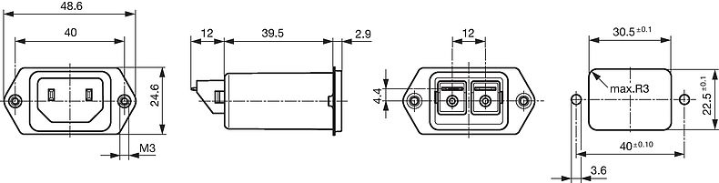
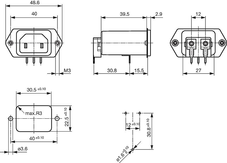
Standard version
|
Screw
|
Front-/Rear-Side
|
Quick connect terminals 6.3 x 0.8 mm
|
I
|
• |
5123.0000.0
|

|
|
10 |
|
|
2
|
Standard version
|
Screw
|
Front-/Rear-Side
|
Quick connect terminals 6.3 x 0.8 mm
|
I
|
• |
5123.0001.0
|

|
|
10 |
|
|
4
|
Standard version
|
Screw
|
Front-/Rear-Side
|
Quick connect terminals 6.3 x 0.8 mm
|
I
|
• |
5123.0003.0
|

|
|
10 |
|
|
4
|
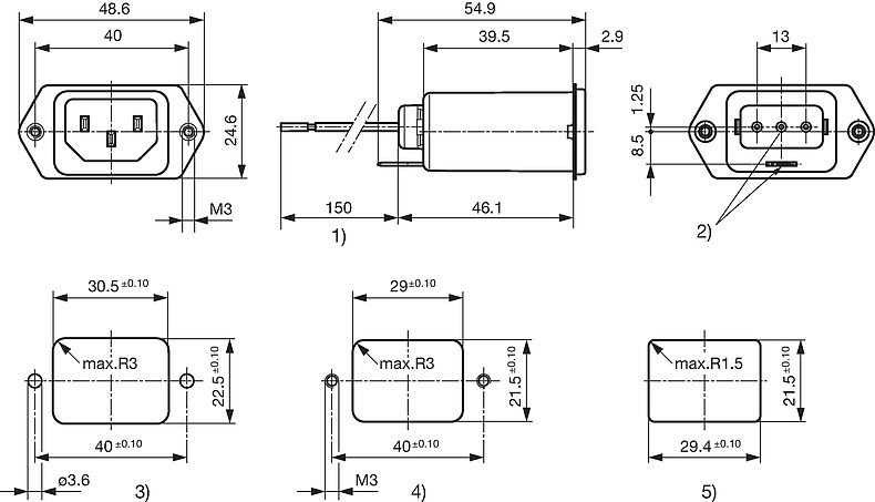
Standard version
|
Screw
|
Front-/Rear-Side
|
Flexible wire AWG18
|
I
|
• |
5123.0233.0
|

|
|
10 |
|
|
6
|
Standard version
|
Screw
|
Front-/Rear-Side
|
Quick connect terminals 6.3 x 0.8 mm
|
I
|
• |
5123.0004.0
|

|
|
10 |
|
|
10
|
Standard version
|
Screw
|
Front-/Rear-Side
|
Quick connect terminals 6.3 x 0.8 mm
|
I
|
• |
5123.0006.0
|

|
|
10 |
|
|
15
|
Standard version
|
Screw
|
Front-/Rear-Side
|
Quick connect terminals 6.3 x 0.8 mm
|
I
|
• |
5123.0007.0
|

|
|
10 |
|
|
1
|
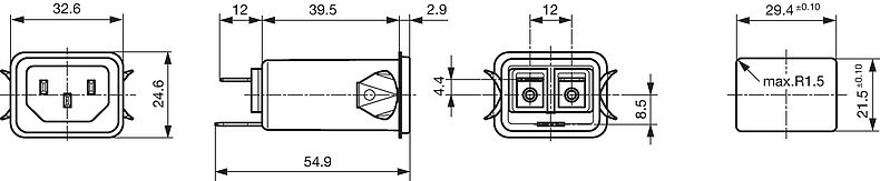
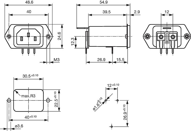
Standard version
|
Screw
|
Rear Side
|
Quick connect terminals 6.3 x 0.8 mm
|
I
|
• |
5123.1000.0
|

|
|
10 |
|
|
2
|
Standard version
|
Screw
|
Rear Side
|
Quick connect terminals 6.3 x 0.8 mm
|
I
|
• |
5123.1001.0
|

|
|
10 |
|
|
4
|
Standard version
|
Screw
|
Rear Side
|
Quick connect terminals 6.3 x 0.8 mm
|
I
|
• |
5123.1003.0
|

|
|
10 |
|
|
6
|
Standard version
|
Screw
|
Rear Side
|
Quick connect terminals 6.3 x 0.8 mm
|
I
|
• |
5123.1004.0
|

|
|
10 |
|
|
10
|
Standard version
|
Screw
|
Rear Side
|
Quick connect terminals 6.3 x 0.8 mm
|
I
|
• |
5123.1006.0
|

|
|
10 |
|
|
10
|
Standard version
|
Screw
|
Rear Side
|
Flexible wire and Earth pin 6.3 x 0.8
|
I
|
• |
5123.1046.0
|

|
|
10 |
|
|
15
|
Standard version
|
Screw
|
Rear Side
|
Quick connect terminals 6.3 x 0.8 mm
|
I
|
• |
5123.1007.0
|

|
|
10 |
|
|
1
|
Medical Version (M5)
|
Snap-in
|
Front Side
|
Quick connect terminals 6.3 x 0.8 mm
|
I
|
• |
5123.2300.0
|

|
|
10 |
|
|
2
|
Medical Version (M5)
|
Snap-in
|
Front Side
|
Quick connect terminals 6.3 x 0.8 mm
|
I
|
• |
5123.2301.0
|

|
|
10 |
|
|
4
|
Medical Version (M5)
|
Snap-in
|
Front Side
|
Quick connect terminals 6.3 x 0.8 mm
|
I
|
• |
5123.2303.0
|

|
|
10 |
|
|
6
|
Medical Version (M5)
|
Snap-in
|
Front Side
|
Quick connect terminals 6.3 x 0.8 mm
|
I
|
• |
5123.2304.0
|

|
|
10 |
|
|
10
|
Medical Version (M5)
|
Snap-in
|
Front Side
|
Quick connect terminals 6.3 x 0.8 mm
|
I
|
• |
5123.2306.0
|

|
|
10 |
|
|
15
|
Medical Version (M5)
|
Snap-in
|
Front Side
|
Quick connect terminals 6.3 x 0.8 mm
|
I
|
• |
5123.2307.0
|

|
|
10 |
|
|
1
|
Medical Version (M5)
|
Screw
|
Front-/Rear-Side
|
Quick connect terminals 6.3 x 0.8 mm
|
I
|
• |
5123.0300.0
|

|
|
10 |
|
|
2
|
Medical Version (M5)
|
Screw
|
Front-/Rear-Side
|
Quick connect terminals 6.3 x 0.8 mm
|
I
|
• |
5123.0301.0
|

|
|
10 |
|
|
4
|
Medical Version (M5)
|
Screw
|
Front-/Rear-Side
|
Quick connect terminals 6.3 x 0.8 mm
|
I
|
• |
5123.0303.0
|

|
|
10 |
|
|
6
|
Medical Version (M5)
|
Screw
|
Front-/Rear-Side
|
Quick connect terminals 6.3 x 0.8 mm
|
I
|
• |
5123.0304.0
|

|
|
10 |
|
|
10
|
Medical Version (M5)
|
Screw
|
Front-/Rear-Side
|
Quick connect terminals 6.3 x 0.8 mm
|
I
|
• |
5123.0306.0
|

|
|
10 |
|
|
15
|
Medical Version (M5)
|
Screw
|
Front-/Rear-Side
|
Quick connect terminals 6.3 x 0.8 mm
|
I
|
• |
5123.0307.0
|

|
|
10 |
|
|
1
|
Medical Version (M5)
|
Screw
|
Rear Side
|
Quick connect terminals 6.3 x 0.8 mm
|
I
|
• |
5123.1300.0
|

|
|
10 |
|
|
2
|
Medical Version (M5)
|
Screw
|
Rear Side
|
Quick connect terminals 6.3 x 0.8 mm
|
I
|
• |
5123.1301.0
|

|
|
10 |
|
|
4
|
Medical Version (M5)
|
Screw
|
Rear Side
|
Quick connect terminals 6.3 x 0.8 mm
|
I
|
• |
5123.1303.0
|

|
|
10 |
|
|
6
|
Medical Version (M5)
|
Screw
|
Rear Side
|
Quick connect terminals 6.3 x 0.8 mm
|
I
|
• |
5123.1304.0
|

|
|
10 |
|
|
10
|
Medical Version (M5)
|
Screw
|
Rear Side
|
Quick connect terminals 6.3 x 0.8 mm
|
I
|
• |
5123.1306.0
|

|
|
10 |
|
|
15
|
Medical Version (M5)
|
Screw
|
Rear Side
|
Quick connect terminals 6.3 x 0.8 mm
|
I
|
• |
5123.1307.0
|

|
|
10 |
|
|
2
|
Medical Version (M5)
|
Screw
|
Front-/Rear-Side
|
Quick connect terminals 6.3 x 0.8 mm
|
II
|
• |
3-128-163
|

|
|
10 |
|
|
4
|
Medical Version (M80)
|
Screw
|
Front-/Rear-Side
|
Flexible wire and Earth pin 6.3 x 0.8
|
I
|
• |
3-119-595
|

|
|
10 |
|
|
6
|
Medical Version (M80)
|
Screw
|
Front-/Rear-Side
|
Quick connect terminals 6.3 x 0.8 mm
|
I
|
• |
5123.0504.0
|

|
|
10 |
|
|
4
|
Medical Version (M80)
|
Screw
|
Rear Side
|
Flexible wire and Earth pin 6.3 x 0.8
|
I
|
• |
3-119-787
|

|
|
10 |
|


")


")